HF Controls Corporation
FPGA Based HFC-6000 Platform - Our Safety Control System
The FPGA version HFC-6000 safety control system is a generic platform design in accordance with all requirements of safety control system in NPPs. The design is mainly focused on the algorithms calculation power and response time through high speed communication links. The complexity in the implementation reflects in many aspects which include automated tools for use in applications and FPGA codes generation and validation, true parallel processing for heavy analog logics and multiple level communication networks. There are two types of system configuration, they are:
Centralized Logic Control Scheme
- HFC-FCPU as controller
- FPGA Processing Units (FPU) as I/O modules
A redundant HFC-FCPU FPGA controller performs the centralized logic control and all FPU modules will be acted as pure I/O modules for it. The F-Link shall become an I/O interface link between HFC-FCPU controller and its FPU I/O modules. Each FPU I/O module handles its on-board I/O process. HFC-FCPU controller and its FPU I/O modules communicate via backplane (for the second rack, it is connected to the first rack via extended cables). This redundant 12.5 MB F-Link allows HFC-FCPU controller updates I/O status and operational database periodically. A redundant G-Link will connect the redundant HFC-FCPU controller and the redundant HFC-FPC08 Gateway controller.
Redundant FCPU and its FPU I/O Modules with redundant Gateway Controller with:
- Safety C-Link to other controllers
- G-Link to Gateway Controller
- F-Link to its FPU I/O Modules
Each redundant FCPU is capable of connecting up to 24 FPU I/O Modules in two (2) racks via 12.5MB F-Link
FPGA HFC-6000 PLATFORM V&V AUTOMATED TOOLS –
HFC’s V&V “OneStep™” Solution to Translate CAD drawings with linked FPGA utility (i.e. communication, diagnostic, algorithms and O.S. utility) into FPGA downloadable codes -
In the development and V&V of the FPGA product, programing and simulation tools qualifications are very important to ensure that the tool performs its intended function and the tool itself shall not introduce errors during the simulation testing process.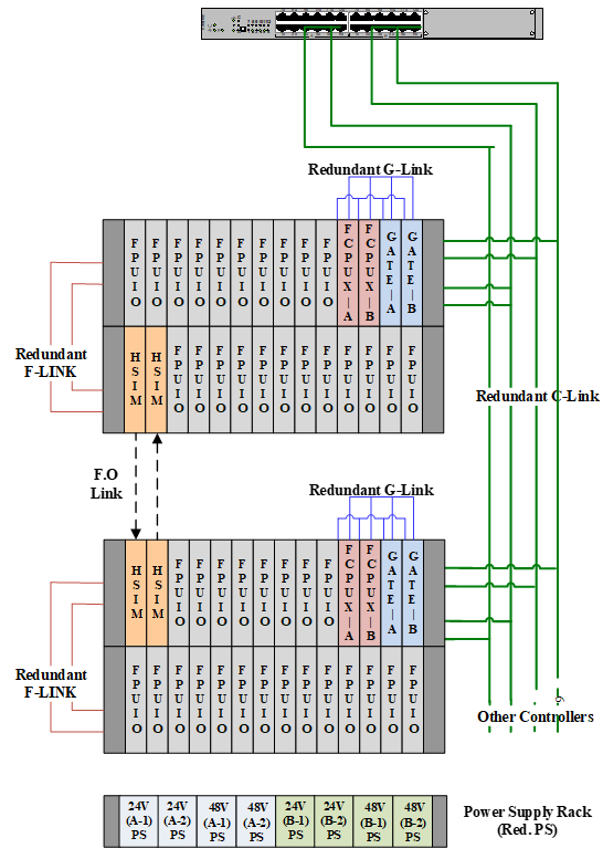
The US NRC/International regulatory guidance for the use of tools for software development and V&V is used for qualifying tools before they are used for safety applications. One of the important tools is the logic development and V&V automation tool – HFC Application Programming Tools for FPU is HFC’s One-Step Automate Logic Generation (One-Step ALG) programming tool under CAD environment. The One-Step ALG is considered to be the ideal auto-documentation tool because it able to generate downloadable FPGA codes directly so that it provides a single documentation source of the entire application programs. The process of this ALG involves the following:
- To edit all control logic diagrams with I/O assignment under CAD environment for a particular application case.
- Compile all edited drawings into text format output files
- Covert those application output files into Verilog format codes
- Link the application Verilog format codes with system level utility codes such as algorithms, communication, etc., under FPGA vendor provided tool.
- After the final synthesis process under FPGA vendor provided utility, the final downloadable FPGA code for the FPU modules is completed. The successful compiled FPGA code can be downloaded into memory of the FCPU / FPU modules.
This FPGA version of the One-Step tool is a critical path for ensuring the correctness of application logics being developed and therefore errors-free in logics development for FPGA applications is achievable.
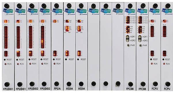
HFC-6000 FPGA HFC-FCPU CONTROLLERS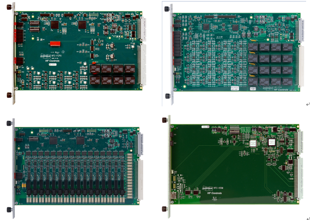
- Complete FPGA architecture controller with diagnostics capabilities
- Dual FPGA structure to protect final output data from Single Event Upset
- Complete diagnostic scheme and self - checking capabilities
- Power on reset circuitry with onboard watchdog timer
- Redundant power feeds with onboard diode auctioneering
- Redundant F-Link and G-Link communications capability
- 16 onboard Dis with status LED indications with fuse protection
HFC-6000 FPGA PROCESSING UNIT (FPU)
COMMON FEATURES
- Dual FPGA based intelligent module diagnostics and self-checking capabilities
- Logic execution capability
- Power on reset circuitry with onboard watchdog timer
- Redundant power feeds with onboard diode auctioneering
- Redundant F-Link communications capability
HFC-FPUD01
FPU with onboard Digital Inputs (DI) & Digital Outputs (DO)
- 16 Digital Input (DI) and 16 Digital Output (DO) channels
- Onboard status LED indications and fuse protection
HFC-FPUD02
FPU with onboard Digital Inputs (DI)
- 32 Digital Input (DI) channels
- Onboard status LED indications and fuse protection
HFC-FPUA
FPU with onboard Analog Inputs (AI)
- 16 Analog Input (AI) channels (4~20 ma/0-5V/0-10v)
- 24-bit A/D converter with advanced signal conditioning
- ±0.1% accuracy and linearity
- Onboard status LED indications and fuse protection
HFC-FPUAO
FPU with onboard Analog Outputs (AO)
- 8 Analog Output (AO) channels (4~20 ma/0-10v)
- 16-bit D/A converter with advanced signal conditioning
- ±0.1% accuracy and linearity
- Configurable set points: last state, board-failure failsafe, and controller-failure failsafe
HFC-FPUL
FPU with onboard Thermocouple (TC) Analog Inputs
- 8 isolated TC Analog Input channels
- FPGA based 24-bit A/D converter with advanced signal conditioning
- ±0.1% accuracy and linearity
- Onboard status LED indications and fuse protection
HFC-FPUM FPU with onboard RTD Analog Inputs
- 8 isolated 3-wire RTD Analog Input channels
- 100 Ohms/ 2K Ohms Platinum
- FPGA based 24-bit A/D converter with advanced signal conditioning
- ±0.1% accuracy and linearity
- Onboard status LED indications and fuse protection
Other FPGA based modules
HFC-HSIM
FPGA based High Speed Interface Module (HSIM)
- Transfer data from F-Link to HSIM Link or
- Transfer data from HSIM Link to F-Link
- High speed and dedicate communication between safety channels or controllers
HFC-DI32IG
FPGA based Digital Input s (DI)
- 32 Digital Input (DI) channels
- Onboard status LED indications
HFC-CIM01
FPGG based Priority Board
- HFC’s Component Interface Module